
Guide to Building Walls with Pumice Blocks: From Selection to Render
Where to use 10, 15, 20 and 25 cm pumice blocks, the difference between masonry mortar and thin-bed adhesive, wetting, column connections, lintels and ring beams, service chases and site rules for crack-free render.
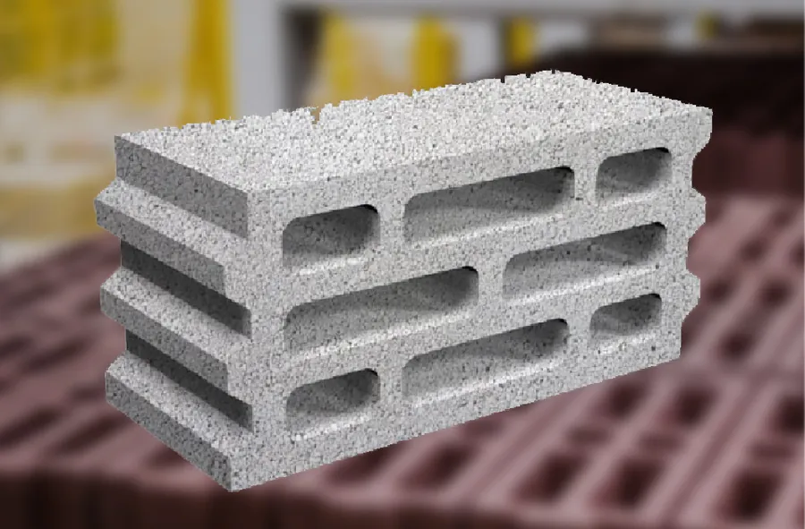
Pumice block is the most widely used material for partition and infill walls: it is light, easy to cut, holds nails and plugs, and contributes to thermal and acoustic insulation. On site, however, what determines the life of the wall is not the block but the workmanship that goes with it. A block chosen at the wrong thickness, a course laid without wetting, a wall end not tied to the column, or a service chase hacked out at random; all of these come back as cracks months after the render is finished. In this guide we explain, from the production plant and from the field, how to choose the block thickness, which binder to use where, how to tie the wall to the frame and how it behaves during an earthquake.
What Is a Pumice Block and Why Is It Light?
A pumice block is a lightweight concrete product whose aggregate is natural pumice. The porous structure within the pumice makes the unit weight of the block markedly lower than that of normal concrete. This single property governs everything the block does on site: the same area of wall imposes less load on the structure, the same bricklayer builds more wall in a day, and the same porous structure makes it harder for both heat and sound to pass through.
The product standard for aggregate concrete masonry units is TS EN 771-3. The standard defines the dimensions and tolerances of the block, its compressive strength, gross dry density, dimensional change (drying shrinkage) and water vapour permeability; the manufacturer declares these values. There are two basic figures to look at when choosing a block: compressive strength and gross dry density. In an infill wall the block is not an element counted as structural in the design; but it must be strong enough to carry its own weight, its render, the cupboards that will be hung on it and the horizontal force generated by its own mass during an earthquake.
The second consequence of lightness concerns the whole building. Infill walls make up a far from negligible part of the dead load of a building. As the weight of the walls falls, so does the load reaching the columns, beams and foundations; and because earthquake force is directly proportional to mass, the seismic load on the building falls too. Choosing pumice block is therefore not only a decision about a walling material but one that eases the structure as well.
The third property is ease of working. The block is cut with a saw, chased with a wall chaser and holds nails and plugs. That ease is also a risk: because it is easy to cut, more is cut than necessary; because chases are easy to make, more chases are made than necessary. We return to both of these points later in the guide.
10, 15, 20 and 25 cm: Which Thickness Goes Where?
Pumice block thickness is chosen according to the job the wall has to do. As the thickness increases, both sound insulation and thermal resistance improve, but usable internal space is lost and cost rises. The usual approach is as follows:
| Thickness | Typical use | Point to watch |
|---|---|---|
| 10 cm | Partitions within a room, behind wardrobes, dressing-room divisions, closing off service shafts | Sound insulation is limited; not to be chosen between a bedroom and a living room. In long walls the risk of going out of plane increases, and an intermediate ring beam or vertical support is needed. |
| 15 cm | Main partition walls within a flat, bathroom and kitchen walls, corridor divisions | The best-balanced option within a flat. In wet-room walls the waterproofing and render system must be correctly built up. |
| 20 cm | One leaf of a separating wall between flats, stair well walls, external infill walls | Between flats, a twin-leaf wall with a cavity gives a markedly better acoustic result than a single-leaf wall. |
| 25 cm | External infill walls, perimeter walls in single-storey buildings, facades where thermal performance is the priority | A thick block does not insulate on its own; an insulation layer is still needed on the facade. Thickness sits alongside insulation, not in place of it. |
The most common mistake in selection is building every wall in one thickness. Making all internal partitions 10 cm saves material but lets neighbouring rooms hear one another; making everything 20 cm loses floor area inside the flat. The right approach is to sort walls by the job they do: thick blocks where noise separation is needed, thin blocks where the wall only divides space.
The second criterion is the height and length of the wall. In rooms with a large storey height, a thin block tends to move out of plane both during and after building. In walls higher than about three metres, either the thickness is increased or the wall is divided in two by an intermediate ring beam across its middle. The same applies to long walls: a long wall with no support at its sides flexes out of its own plane.
The third criterion is services. If hot and cold water pipes or a thick electrical conduit are to run inside the wall, the chase depth will eat into the section of the wall and the thickness is chosen accordingly. Water services are not buried in a 10 cm partition; they are resolved in a wall of at least 15 cm or in a separate shaft.
Masonry Mortar or Thin-Bed Adhesive?
There are two jointing methods for a pumice wall, and each calls for a different product and different workmanship.
Conventional masonry mortar (thick bed): The bed joint is around one and a half centimetres thick. This is the only correct method for blocks with wide dimensional tolerances and unground faces; the mortar absorbs the height differences between blocks and you level each course with mortar. The mortar itself may be a ready-mixed masonry mortar or a cement-sand mortar batched on site. What matters is that the consistency of the mortar suits the suction of the wall and that the perpend joints are filled as well. The job most often skipped on site is filling only the bed joint and leaving the perpend empty; an empty perpend is both a sound bridge and the starting point of render cracking.
Thin-bed adhesive: The joint thickness comes down to a few millimetres. This method can only be used with blocks that have ground faces and tight dimensional tolerances, because the mortar can no longer absorb differences in height. Its advantages are clear: the thermal and acoustic bridge through the joint is reduced, the wall comes out truer, the render thickness falls and the work goes faster. Its disadvantage is that the first course must be levelled perfectly. In a thin-bed system a one-millimetre error made in the first course cannot be corrected in the courses above.
Whichever method you choose, two rules do not change. First, adhesive and masonry mortar are not mixed; putting one course of thick mortar into a thin-bed system creates a difference in level and in stiffness in the wall. Second, mortar or adhesive is used within its open time. A block set on mortar that has skinned over on the board in summer heat will not bond; that wall looks sound under the render but its joints have no adhesion.
A third point is staggered bonding. The blocks are laid offset so that the perpend joints do not line up one above another. Perpends stacked above one another create a line of weakness running the full height of the wall, and the slightest movement produces a crack along that line. The offset must be a substantial proportion of the block length; a stagger of a few centimetres does not count as bonding.
Wetting: Why Blocks Are Dampened, and How They Should Not Be
Pumice is a porous material and it absorbs water. When you place a dry block on wet mortar, the block draws the mixing water out of the mortar. Starved of water, the mortar cannot complete the hydration of the cement; it fails to set and remains a dusty, weak joint. On site this shows up a few months later as straight cracks along the joint lines.
The correct practice is to dampen the blocks before laying, not to soak them. Dampening means the surface of the block and the pores near the surface are saturated while the interior stays dry. In practice they are wetted with a hose or a spray and laying begins once the free water on the surface has drained away. A block with water running off it thins the mortar and slides on it; the wall will not hold its level and the joint is weakened.
How much wetting is needed varies with the weather. In summer, on a hot and windy day, both block and mortar lose water quickly; wetting is more generous and the finished wall is dampened again during the day. In cool, damp weather wetting is reduced. On days with a risk of frost, water freezing inside a wet block is a separate cause of damage; walls are not built at temperatures below zero.
With thin-bed adhesive the logic of wetting changes. Most of these products contain water-retaining additives and generally require no wetting; it is enough for the face of the block to be free of dust. Adhesive spread on a surface still covered in cutting dust bonds to the dust, not to the block. In short: with thick mortar it is moisture that matters, with a thin bed it is cleanliness.
One more point: stacking blocks on site. Blocks left directly on the ground and exposed to rain draw water from below and the bottom courses become saturated. Stacking on pallets, isolated from the ground and covered over, both preserves the moisture balance and reduces corner breakages. A wall built with blocks with broken corners is a wall whose joints have to be packed with mortar and whose render ends up thicker.
Column-to-Wall Connection and Earthquake Behaviour
An infill wall is an element not counted as structural in the design but one that certainly takes part in an earthquake. Two kinds of action arise during an earthquake: the demand in the plane of the wall caused by the deformation of the frame, and the inertia force perpendicular to the wall arising from its own mass. The second tries to overturn the wall out of its plane. A significant proportion of the injuries and loss of life in earthquakes is caused by infill walls overturning in buildings whose frames remained standing.
Tying the infill wall to the frame is therefore not a preference but a requirement of the earthquake code in force. On site the connection is made at the following points:
- To column and shear wall faces: Along the edge where the wall abuts the column, anchor bars (chemical anchors, or starter bars left in during the concrete pour) are fixed at set course intervals and extended into the bed joint. Simply butting the wall against the column with mortar means a joint that opens at the first tremor.
- In the bed joints: Mesh or bar reinforcement running along the wall is placed in the joints the anchors extend into. This reinforcement turns an individual anchor into a continuous line and improves the out-of-plane behaviour of the wall.
- To the beam above: The gap between the top course of the wall and the underside of the beam is not left open. It is packed tightly some time after the wall is built, once the wall has finished settling. A top joint left open means the wall has no support at the top; under earthquake loading the wall overturns from here first.
- At free ends: Walls with one end against a column and the other end free (balcony division walls, low parapets) must be supported at the free end by a vertical element or a return.
Then there is the position of the openings in the wall. Door and window openings disrupt the stiffness of the wall and create stress concentrations at the corners of the openings. The diagonal cracks that start at the corners of openings are seen in almost every building and their source is well known. Reinforcing the edges of openings with reinforced joints and providing proper bearing for the lintel prevents most of these cracks.
Finally, watch out for the short column effect. Walls that enclose only part of a column, with a window opening above them (particularly strip windows at basement and ground floor level), shorten the free length of the column and severely overstress it during an earthquake. This is resolved by design and detailing, not by the walling work; do not raise a wall or change an opening level on your own initiative on site.
Lintel and Ring Beam: The Top of the Opening, the Waist of the Wall
A lintel is the element that transfers the wall load above a door or window opening to either side of it. It may be a precast lintel beam, a cast-in-place reinforced concrete lintel, or built with special blocks that contain a lintel channel. It has three rules: adequate depth, adequate reinforcement and adequate bearing length. The last is the mistake most often made on site; the lintel is set almost exactly into the opening, with only a few centimetres of bearing at each end. The load then concentrates on the narrow strip of wall at the edge of the opening and cracking starts from the ends of the lintel. The lintel must bear on the wall at both ends over a visible bearing length proportional to the width of the opening.
The space under the lintel is not left open. If the gap between the lintel above the opening and the frame is left unfilled, load bears on a frame that was never meant to carry any; the consequences range from a casement that will not open to broken glass. The lintel is also planned together with any roller shutter or blind box; letting the box take the place of the lintel leaves the head of the opening unsupported.
A ring beam is the horizontal element that braces the wall at its waist. In reinforced concrete frame structures the columns and beams take on most of this duty; but an intermediate ring beam is needed in tall rooms, in long walls, in garden walls and in the perimeter walls of single-storey buildings. The ring beam frames the wall horizontally, improves its out-of-plane behaviour and limits movement at the perpend joints. In free-standing walls such as garden walls, leaving out the ring beam produces a wall that leans at the first strong wind or ground settlement.
The surface the wall sits on belongs to the same family of issues. The wall must bear on a clean, true support, not on blinding concrete covered with debris and dust. In wet-room walls, casting a low concrete upstand beneath the wall, up which the waterproofing can be carried, prevents the bottom courses from being constantly wetted. A wet bottom course blisters the render and lifts the paint; this is the source of most of the blistering along the bottom line of bathroom walls.
Cutting Service Chases: Without Weakening the Wall
The ease with which pumice block can be worked makes it the point at which the wall suffers most during services installation. The rules for cutting chases are simple, but they are rarely all followed on site:
- Cut chases, do not break them out. Two parallel cuts are made with a wall chaser or chase-cutting machine and the material between them is cleaned out. A chase opened with a chisel and sledgehammer cracks the block well beyond the width of the chase; these cracks stay hidden under the render and show through months later.
- Prefer vertical chases. A horizontal chase cuts right through the wall at one section and directly reduces its out-of-plane strength. In electrical work, sockets and switches are reached by vertical drops wherever possible, and unavoidable horizontal runs are kept short.
- Limit the depth of the chase. The chase depth must not exceed a small proportion of the block thickness, and chases must not be cut in the same position on both faces. Chases opposite one another all but split the wall in two at that section.
- Keep away from the edges of openings. A chase running right beside a door or window corner weakens a zone that already carries a stress concentration; the crack starts here.
- Fill the chase before rendering. Once the pipe is in place, the chase is filled with plaster or a suitable repair mortar and render mesh is applied over it. An empty chase left directly under the render produces the linear crack known on site as a pipe trace.
There is also the question of sequence: first-fix services are installed after the wall has been built and the mortar has set sufficiently. Cutting chases in a freshly built wall tears open joints that have not yet gained strength. In the same way, rather than driving plugs straight into a thin block for a heavy cupboard, a boiler or a basin bracket, planning built-in blocking or a metal plate at the fixing points spreads the load into the wall. A suspended load bearing on the wall as a point load usually results not in the block breaking but in that part of the wall flexing forward.
Preparation Before Rendering and the Causes of Cracking
Render is not a layer that hides the faults of a wall; it is a thin skin that carries every movement of the wall straight to the surface. What is done before rendering starts therefore matters more than the quality of the render itself:
- The wall must have cured. A newly built wall is not rendered before its mortar has set and it has finished settling. A wall rendered too early completes its settlement through the render.
- The surface is cleaned. Squeezed-out mortar is scraped off, dust is removed and oil and formwork residue are cleaned away.
- Voids are filled. Empty perpend joints, broken block corners, service chases and gaps at column-to-wall junctions are made good before rendering. Render cannot fill these voids; it only covers them over.
- Mesh is applied at the boundaries between different materials. The vertical line where a concrete column meets the pumice wall, the underside of beams, the edges of lintels and the line above a service chase. These are the places where two different materials move differently and cracking is unavoidable; mesh does not prevent the crack but distributes it and makes it invisible to the eye.
- Suction is balanced. Pumice draws water out of the render. Render applied before the suction of the surface has been evened out with a suitable primer or spatterdash coat fails to bond and in time lifts off in sheets.
- Thickness is checked. If the plane of the wall is out, the render thickens to cover it; thick render strains its own bond under its weight and produces shrinkage cracking. A well-built wall means thin render.
The cracks we see on site nearly always come back to one item on this list. Straight horizontal cracks along the joint lines point to building on dry blocks or to mortar that has lost its water. Vertical cracks running along a column mean the junction between the concrete and the wall was left without mesh. Diagonal cracks running from the corners of openings mean insufficient lintel bearing or missing corner reinforcement. Fine linear cracks mean a service chase that was never filled. A horizontal opening under a beam means the top joint was never packed. A vertical line running down the wall means the blocks were laid without staggering the joints. The shape of the crack tells you directly which step was skipped; that is why you have to look at the crack before you start repairing it.
A sound wall starts with the right product as much as with the right workmanship: a wall built with blocks of tight dimensional tolerance, declared strength and proper stacking will crack less for the same workmanship. At Bodrum Boru we produce 10, 15, 20 and 25 cm pumice blocks and 25 and 30 cm pumice hollow floor blocks at our Milas facility; for thickness and quantity planning to suit your project you can reach us through our contact page.
Frequently asked questions
Should pumice blocks be wetted before a wall is built?
If conventional masonry mortar is used, yes, they must be dampened. A dry block absorbs the mixing water from the mortar and the mortar cannot set; the result is straight cracks along the joint lines. Dampening means wetting, not soaking: the surface should be saturated and the interior dry, and laying should begin once the free water has drained away. With thin-bed adhesive it is not wetting but a dust-free surface that matters.
Which thickness should be used for a wall between flats?
Because sound insulation is the priority, a single thin leaf is not enough. In practice a thickness of 20 cm or more, or a twin-leaf wall with a cavity, is used; the twin-leaf solution is markedly better acoustically. If service chases are to be cut into the wall, the thickness must be increased accordingly, and chases must not be cut in the same position on opposite faces.
How is an infill wall tied to a column?
Anchor bars are fixed into the face of the column or shear wall at set course intervals and extended into the bed joint; within that joint a continuous line is formed with reinforcement running along the wall. The gap between the top of the wall and the underside of the beam is packed tightly once the wall has finished settling. These connections prevent the wall from overturning out of plane during an earthquake.
Is it harmful to cut a horizontal service chase in a wall?
Yes. A horizontal chase cuts right through the wall at one section and reduces its out-of-plane strength. Sockets and switches should be reached by vertical drops and unavoidable horizontal runs kept short. Chases should be cut with a chase-cutting machine rather than broken out with a chisel, kept limited in depth, and filled with repair mortar and covered with mesh before rendering.
What is the most common cause of cracking in render?
The shape of the crack tells you its cause. Straight horizontal cracks along the joint lines point to building on dry blocks or to mortar that has lost its water; vertical cracks running along a column mean no mesh was applied at the concrete-to-wall junction; diagonal cracks from the corners of openings mean insufficient lintel bearing; and fine linear cracks mean a service chase that was never filled.
Does a pumice block provide thermal insulation on its own?
Thanks to its porous structure it contributes to thermal resistance and offers a clear advantage over dense concrete, but on its own it does not take the place of facade insulation. On external walls an insulation layer must be planned alongside a thick block. Block thickness complements insulation; it is not an alternative to it.
Related articles
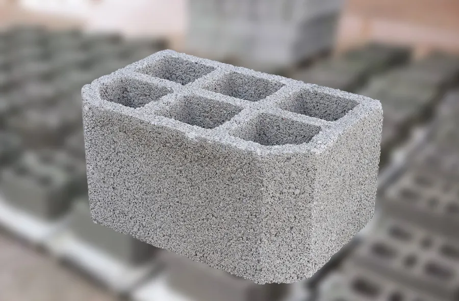
What Is a Hollow Block Floor System, and Where and How Is It Built?
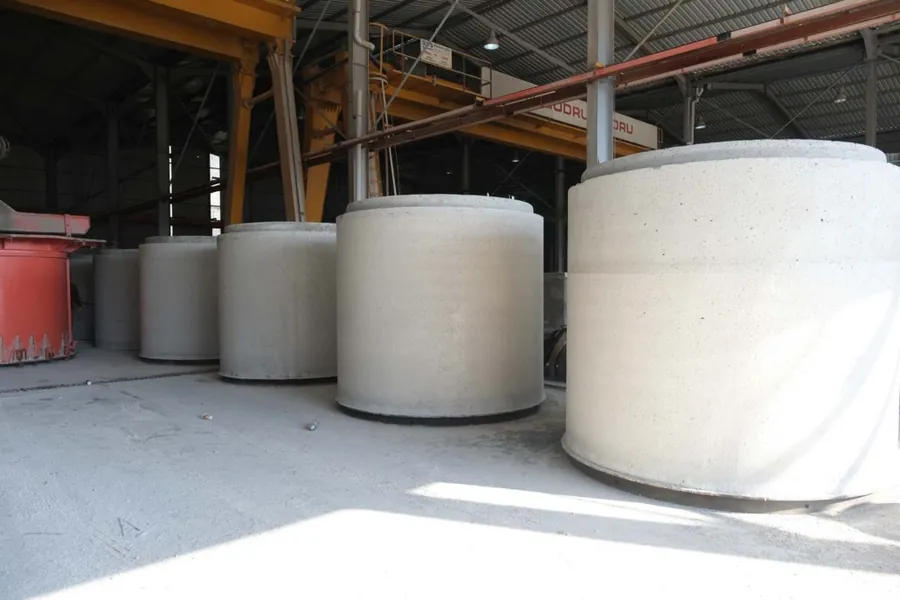
Choosing the Strength and Load Class of Concrete Pipe: What to Check in the Design
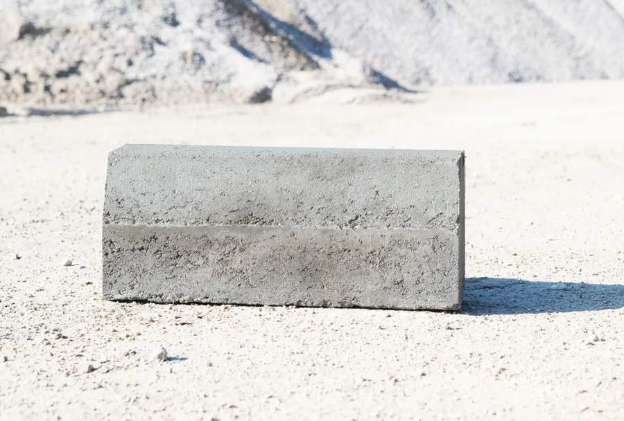
Kerb Stone Types and Laying Rules: What to Watch on Site
Stormwater Drainage: Channels, Grating Classes and Ditch Elements
Manhole (Inspection Chamber) Elements and Installation: From Base to Cover
Laying Interlocking Pavers: Ground Preparation, Sand Bed and Joints
Laying Concrete Pipes: Trench, Bedding, Seals and Joints
Let us prepare a product and delivery plan for your project
Contact our plant management for stock availability, size options and a price quote. Same-day delivery from our facility at the centre of the Milas–Bodrum axis to Milas, Bodrum, Muğla, Didim and the surrounding areas.